
|
Boiler model |
K-140M1 |
K-320M1 |
K-500M1 |
K-720M1 |
K-950M1 |
|
|
Boiler type |
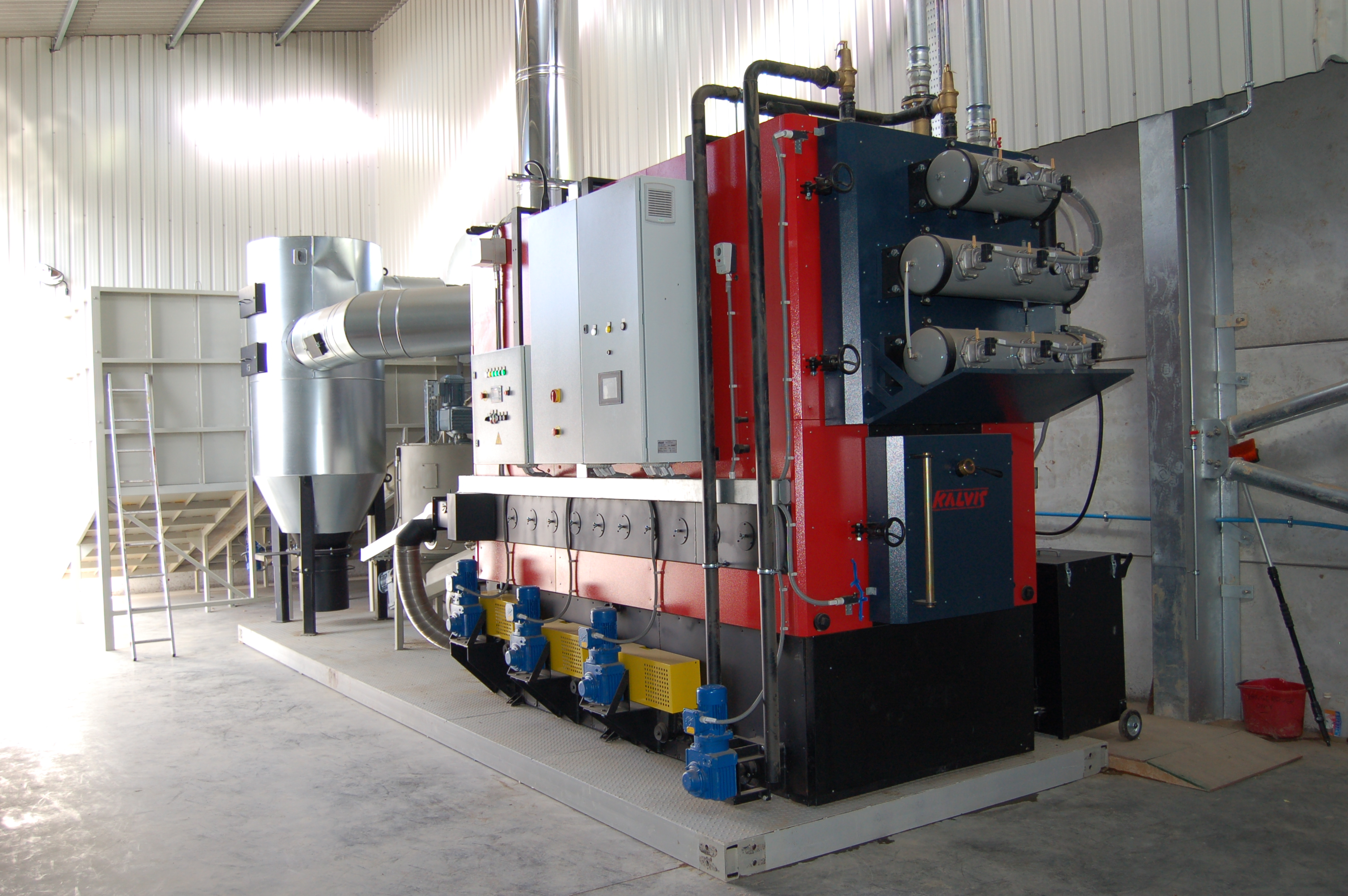
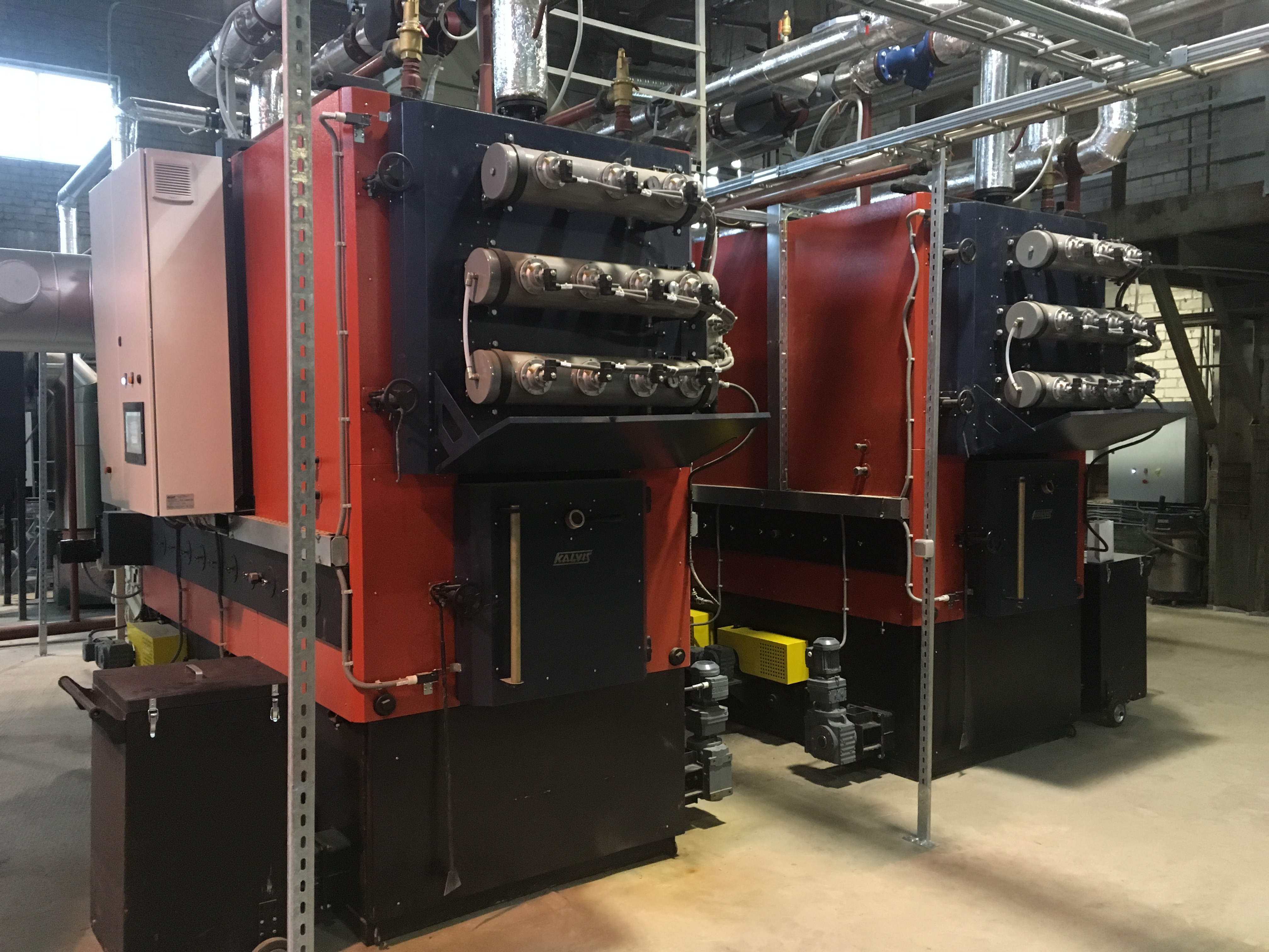
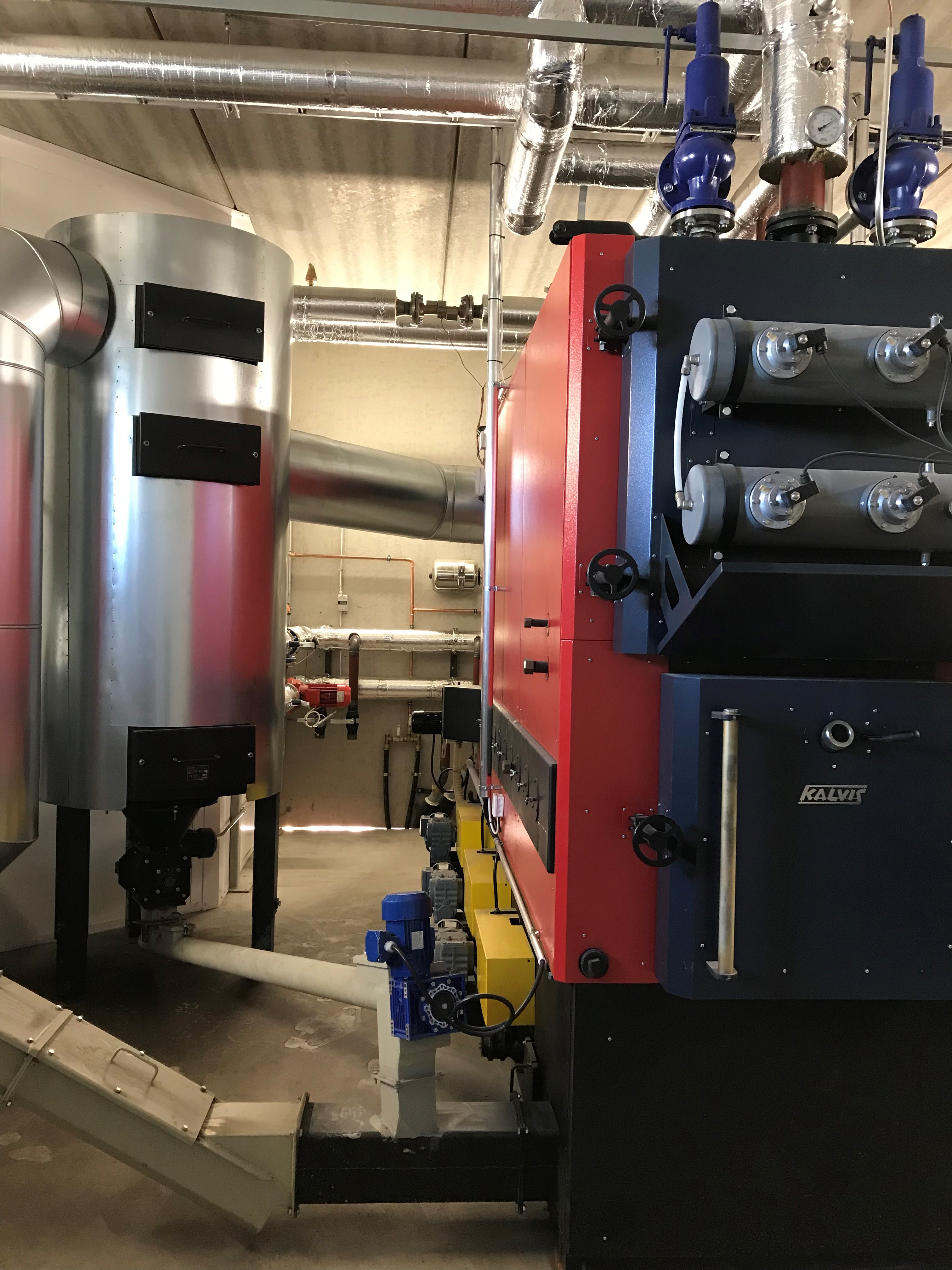
Hot water boiler with moving fire grate, steel, shell boiler |
|||||
|
Nominal heating output (QN), kW |
140 |
320 |
500 |
720 |
950 |
|
|
Minimal heating output (Qmin), kW |
42 |
96 |
150 |
216 |
285 |
|
|
Efficiency, not less than % |
85 |
85 |
85 |
85 |
85 |
|
|
Main used fuels |
Saw dust, wood chips with moist content not exceeding 40% (length not greater than 50mm) . |
|||||
| Other fuels permitted for firing | Fire wood, waste wood, peat and saw dust briquettes, coal | |||||
|
Fuel consumption, kg/h |
62 |
141 |
220 |
317 |
399 |
|
|
Loading opening BxH, mm |
400×450 |
400×450 |
600×620 |
600×620 |
600×620 |
|
|
Combustion chamber |
H, mm |
400 |
500 |
500 |
640 |
700 |
|
B, mm |
640 |
940 |
940 |
940 |
910 |
|
|
L, mm |
1000 |
1640 |
1640 |
2590 |
2590 |
|
|
volume, dm3 (l) |
260 |
770 |
770 |
1558 |
1650 |
|
|
Aerodynamic resistance at QN, not more than, Pa |
180 |
270 |
300 |
320 |
340 |
|
|
Exhaust temperature at boiler flue outlet, °C |
185 |
185 |
185 |
185 |
185 |
|
|
Exhaust volume, m3/h |
585 |
1414 |
2070 |
2860 |
4280 |
|
|
Flue outlet dimensions, mm |
Ø250 |
Ø325 |
Ø350 |
Ø350 |
Ø400 |
|
|
Water operating pressure, bar (MPa) |
6 (0,6) |
6 (0,6) |
6 (0,6) |
6 (0,6) |
6 (0,6) |
|
|
Minimum return water temperature during operation, ºC |
60 |
|||||
|
Maximum permitted operating water temperature, ºC |
110 |
110 |
110 |
110 |
110 |
|
|
Water flow, at Δt =20 ºC, t/h |
6,02 |
13,76 |
21,29 |
30,96 |
40,85 |
|
|
Minimum water flow, t/h |
2,41 |
5,50 |
8,51 |
12,38 |
16,34 |
|
|
Hydraulic resistance at Δt =20 ºC, mm of H2O |
0,014 |
0,134 |
0,144 |
0,282 |
0,430 |
|
|
Water volume in the boiler, m³ |
0,58 |
1,15 |
1,66 |
2,2 |
3 |
|
|
Heat exchange area, m² |
10,3 |
25,8 |
32 |
43 |
73 |
|
|
Connection pipes |
Nominal diameter, mm (inches) |
65 (2½”) |
65 (2½”) |
80 (3″) |
80 (3″) |
80 (3″) |
|
flange diameter, Ø mm |
160 |
160 |
185 |
185 |
185 |
|
|
Mass (not greater than), kg |
2500 |
4900 |
5820 |
7400 |
9700 |
|
|
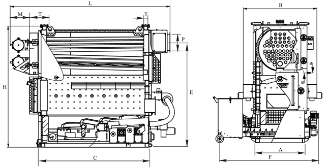
Boiler type |
K-140M1 |
K-320M1 |
K-500M1 |
K-720M1 |
K-950M1 |
|
H, mm |
2105 |
2480 |
2610 |
2765 |
2950 |
|
B, mm |
1300 |
1500 |
1630 |
1630 |
1840 |
|
L, mm |
1900 |
2810 |
2840 |
3640 |
4180 |
|
A, mm |
800 |
1000 |
1400 |
1400 |
1400 |
|
C, mm |
1400 |
2160 |
2620 |
2920 |
3220 |
|
D, mm |
486 |
746 |
846 |
900 |
900 |
|
E, mm |
1534 |
2154 |
2370 |
2520 |
2520 |
|
F, mm |
1500 |
1970 |
2400 |
2400 |
2400 |
|
M, mm |
304 |
374 |
400 |
400 |
400 |
|
P, mm |
Ø240 |
Ø325 |
Ø380 |
Ø380 |
Ø480 |
|
T, mm |
Ø76 |
Ø76 |
Ø89 |
Ø89 |
Ø89 |
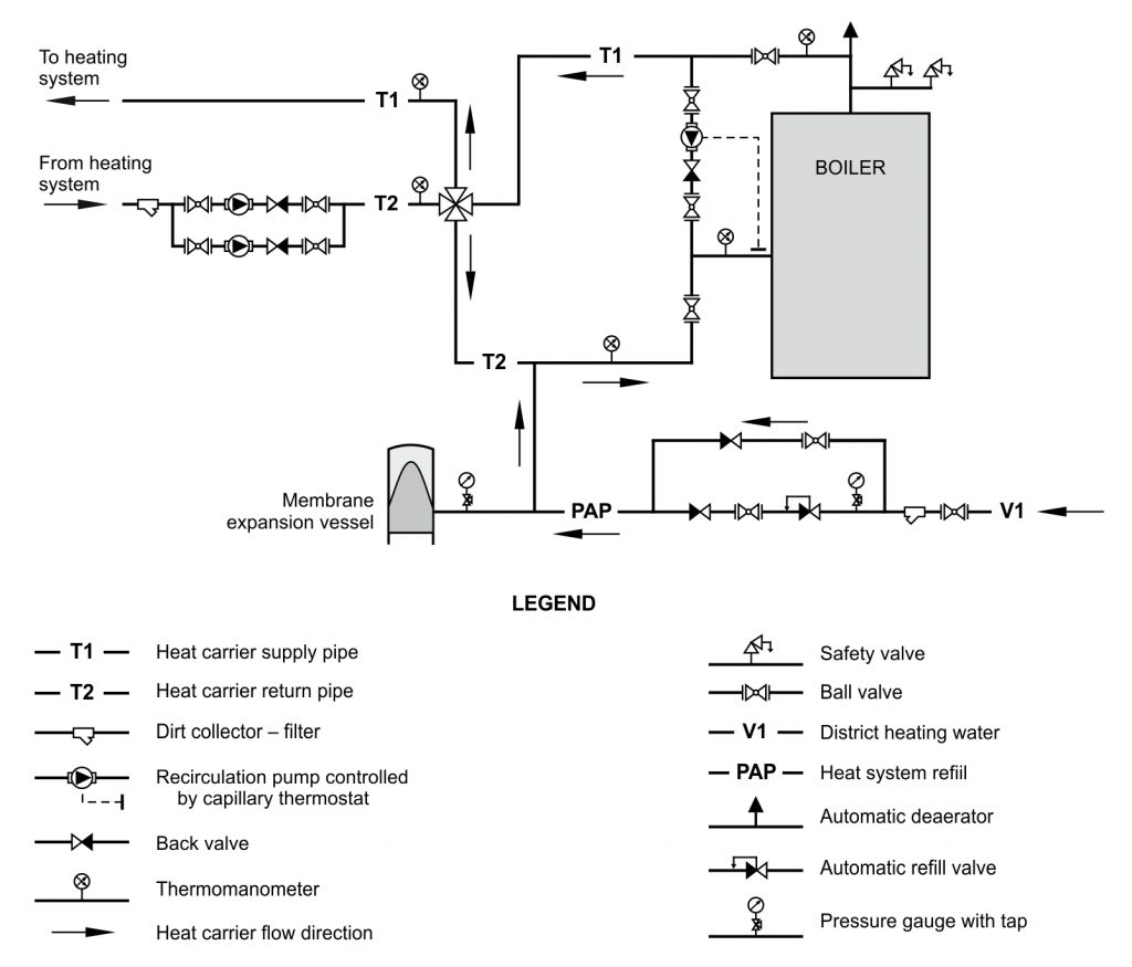
Recommended connection to the heating system diagram: