|
Boiler model
|
|
K-100
|
K-140
|
K-190
|
K-220
|
K-250
|
K-320
|
K-400
|
K-500
|
K-600
|
K-700
|
K-950
|
K-1250
|
|
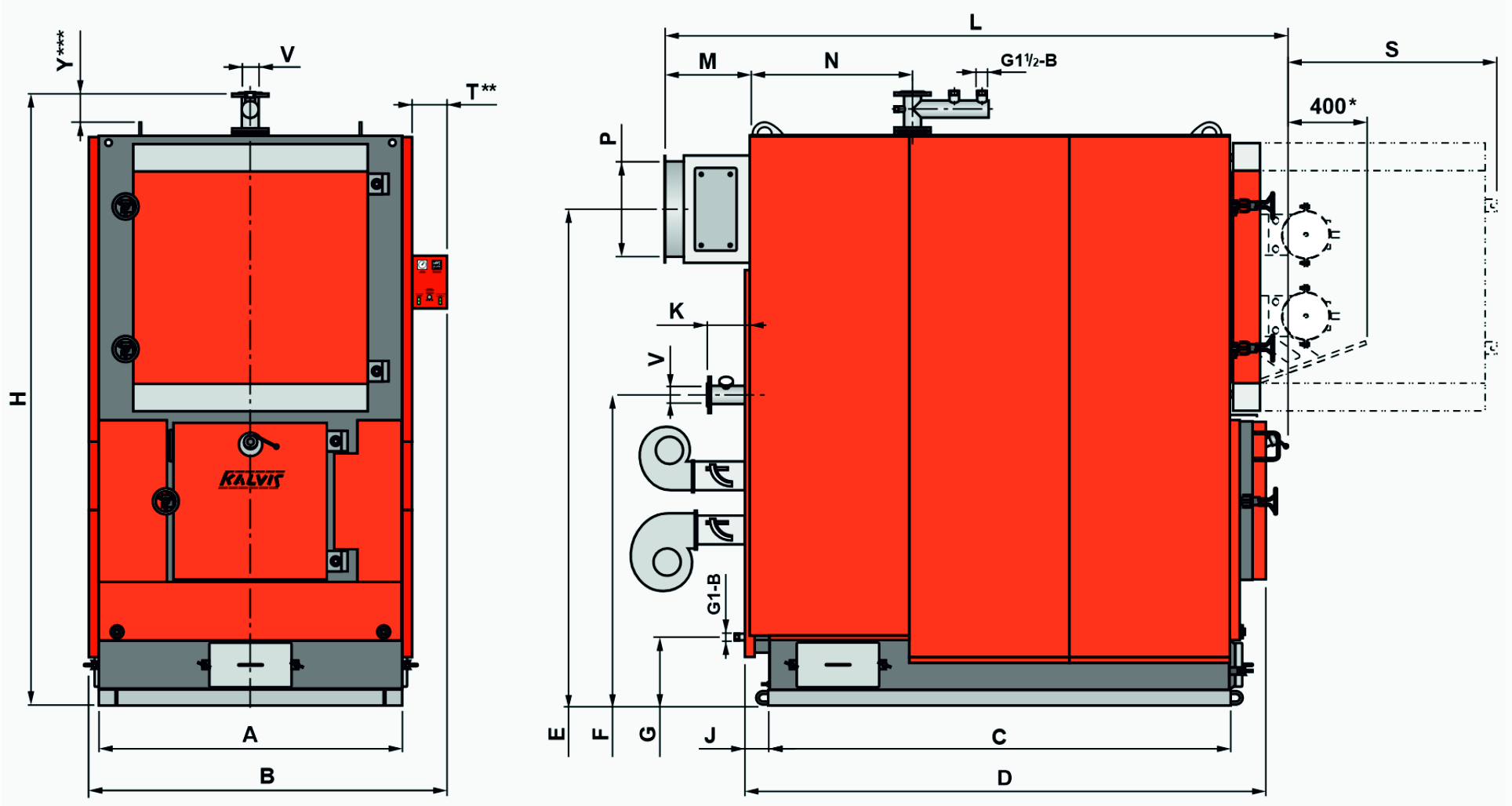
H
B
L
|
mm
|
1960
1000
1510
|
1960
1000
1710
|
2280
1200
1860
|
2280
1200
2060
|
2280
1200
2250
|
2740
1460
2260
|
2740
1460
2460
|
2870
1460
2850
|
2980
1610
2900
|
2980
1610
3090
|
3180
1840
3150
|
3180
1840
3550
|
|
A
|
710
|
710
|
890
|
890
|
890
|
1090
|
1090
|
1090
|
1255
|
1255
|
1480
|
1480
|
|
C
|
930
|
1125
|
1195
|
1390
|
1585
|
1505
|
1700
|
1890
|
2085
|
2285
|
2370
|
2760
|
|
D
|
1180
|
1385
|
1435
|
1680
|
1825
|
1815
|
2000
|
2190
|
2375
|
2565
|
2700
|
3095
|
|
E
|
1620
|
1620
|
1920
|
1920
|
1920
|
2240
|
2240
|
2364
|
2445
|
2475
|
2545
|
2545
|
|
G
|
365
|
365
|
365
|
365
|
365
|
365
|
365
|
345
|
355
|
355
|
350
|
350
|
|
F
|
1120
|
1120
|
1300
|
1300
|
1300
|
1490
|
1490
|
1640
|
1670
|
1670
|
1605
|
1605
|
|
J
|
100
|
100
|
100
|
120
|
100
|
110
|
110
|
110
|
105
|
105
|
120
|
120
|
|
M
|
260
|
260
|
270
|
270
|
270
|
380
|
380
|
380
|
400
|
400
|
395
|
395
|
|
P
|
240×240
|
240×240
|
290×290
|
290×290
|
290×290
|
Ø325
|
Ø325
|
Ø380
|
Ø380
|
Ø480
|
Ø480
|
Ø480
|
|
S
|
560
|
560
|
700
|
700
|
700
|
850
|
850
|
1060
|
1190
|
1190
|
1060
|
1060
|
|
T **
|
130
|
130
|
130
|
130
|
130
|
180
|
180
|
180
|
180
|
180
|
180
|
180
|
|
V
|
Ø65
|
Ø65
|
Ø65
|
Ø65
|
Ø65
|
Ø80
|
Ø80
|
Ø80
|
Ø80
|
Ø80
|
Ø80
|
Ø80
|
|
Y ***
|
–
|
–
|
–
|
–
|
–
|
130
|
130
|
235
|
235
|
235
|
235
|
235
|
* The length of the boiler with the installation of a pneumatic cleaner on the front doors of the heat exchanger: L + 400
** During transportation, if it is necessary to reduce the width of the boiler, the electric control panel can be removed: B – T
*** During transportation, if it is necessary to reduce the height of the boiler, the boilers Kalvis-320 … Kalvis-1250 can have the hot water branch with flange removed: H – Y