
|
Boiler model |
|
K-100M |
K-140M |
K-190M |
K-250M |
K-320M |
K-400M |
K-500M |
K-600M |
K-720M |
K-850M |
K-950M |
K-1250M |
K-1500M |
|
Nominal output |
kW |
95 |
140 |
190 |
250 |
320 |
400 |
495 |
600 |
700 |
850 |
950 |
1250 |
1500 |
|
Efficiency * |
% |
82 |
||||||||||||
|
Fuel used |
|
Saw dust, Chips (length not greater than 50mm), fire wood, waste wood, saw dust or peat briquettes |
||||||||||||
|
Fuel consuption |
Kg/h |
39 |
54 |
74 |
97 |
124 |
155 |
194 |
233 |
280 |
330 |
369 |
486 |
583 |
|
Operating pressure, max./min. |
bar (MPa) |
2,5 (0,25) / 6,0 (0,6) |
||||||||||||
|
Mass |
kg |
800 |
900 |
110 |
2000 |
1900 |
2700 |
3100 |
4100 |
4330 |
4700 |
5100 |
8750 |
9600 |
* Parameters are given using 35 % moisture fuel (Mixture: 35 % humidity chips + 35 % humidity sawdust, proportion 50/50; 2702 kcal/kg).
|
Boiler model |
|
K-100M |
K-140M |
K-190M |
K-250M |
K-320M |
K-400M |
K-500M |
K-600M |
K-720M |
K-850M |
K-950M |
K-1250M |
K-1500M |
|
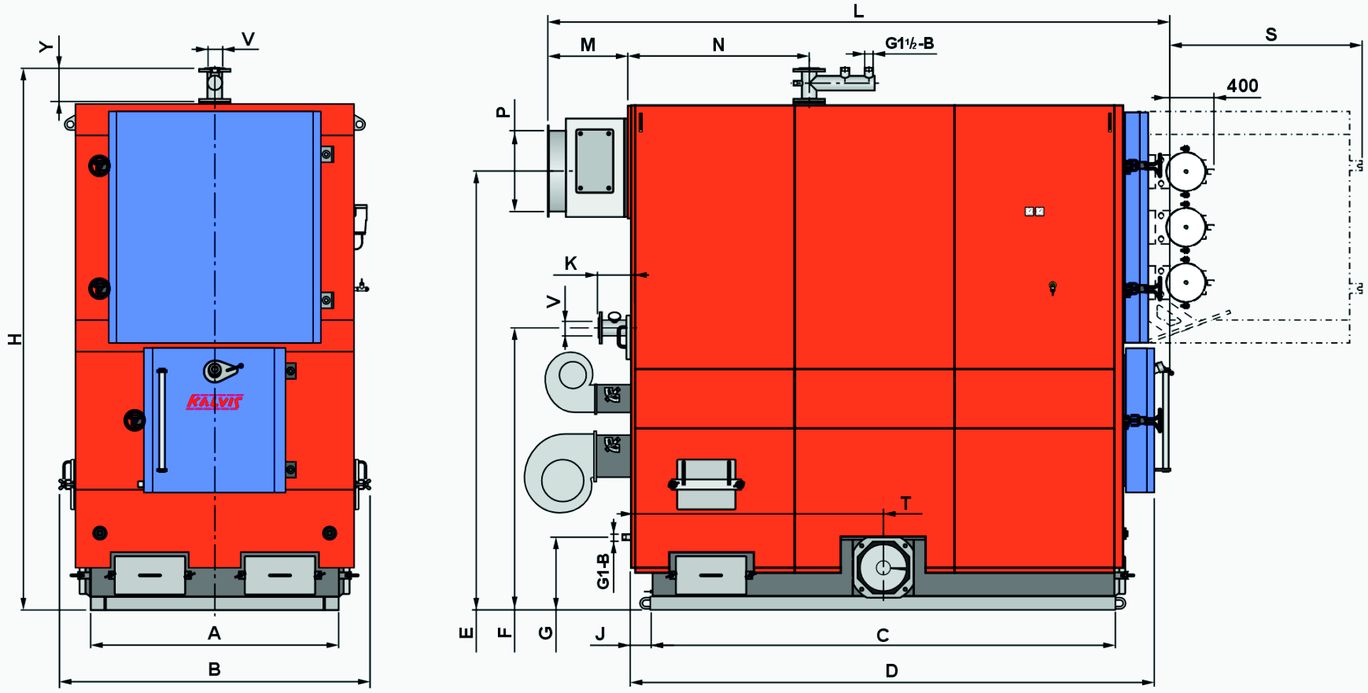
H |
mm |
1940 |
1940 |
2260 |
2260 |
2260 |
2690 |
2730 |
2960 |
2970 |
2970 |
3180 |
3280 |
3280 |
|
B |
970 |
970 |
1140 |
1200 |
1300 |
1470 |
1460 |
1650 |
1610 |
1620 |
1600 |
1860 |
1860 |
|
|
L |
1510 |
1710 |
1830 |
2220 |
2220 |
2460 |
2460 |
2660 |
2990 |
3090 |
3350 |
3700 |
3700 |
|
|
A |
710 |
710 |
890 |
890 |
890 |
1090 |
1090 |
1255 |
1255 |
1255 |
1255 |
1480 |
1480 |
|
|
C |
930 |
1125 |
1195 |
1585 |
1585 |
1505 |
1700 |
1890 |
2085 |
2285 |
2285 |
2760 |
2760 |
|
|
D |
1180 |
1375 |
1520 |
1825 |
1825 |
1815 |
2010 |
2190 |
2375 |
2565 |
2590 |
3120 |
3120 |
|
|
E |
1620 |
1620 |
1900 |
1900 |
1900 |
2240 |
2260 |
2445 |
2455 |
2475 |
2660 |
2610 |
2610 |
|
|
F |
1120 |
1120 |
1300 |
1300 |
1300 |
1505 |
1505 |
1675 |
1675 |
1675 |
1855 |
1685 |
1685 |
|
|
G |
345 |
345 |
345 |
345 |
345 |
355 |
355 |
355 |
355 |
360 |
355 |
430 |
430 |
|
|
J |
100 |
100 |
140 |
140 |
140 |
130 |
135 |
105 |
105 |
105 |
120 |
120 |
120 |
|
|
K |
125 |
125 |
135 |
135 |
135 |
185 |
185 |
220 |
220 |
220 |
205 |
190 |
190 |
|
|
M |
230 |
230 |
235 |
235 |
235 |
530 |
480 |
410 |
530 |
405 |
700 |
490 |
490 |
|
|
N |
340 |
340 |
560 |
560 |
560 |
625 |
675 |
755 |
755 |
825 |
840 |
1060 |
1060 |
|
|
P |
240×240 |
240×240 |
290×290 |
290×290 |
290×290 |
Ø325 |
Ø325 |
Ø380 |
Ø380 |
Ø480 |
Ø480 |
Ø480 |
Ø480 |
|
|
S |
560 |
560 |
700 |
700 |
700 |
850 |
850 |
1060 |
1190 |
1190 |
1060 |
1060 |
1060 |
|
|
T * |
565 |
665 |
725 |
960 |
930 |
910 |
985 |
1020 |
1130 |
1210 |
1225 |
1500 |
1500 |
|
|
V |
Ø65 |
Ø65 |
Ø65 |
Ø65 |
Ø65 |
Ø80 |
Ø80 |
Ø80 |
Ø80 |
Ø80 |
Ø80 |
Ø114 |
Ø114 |
|
|
Y ** |
– |
– |
– |
– |
– |
– |
125 |
235 |
235 |
235 |
235 |
285 |
285 |
* The length of the boiler with the installation of a pneumatic cleaner on the front doors of the heat exchanger (L + 400).
*** During transportation, if it is necessary to reduce the height of the boiler, the boilers Kalvis-500M … Kalvis-1500M can have the hot water branch with flange removed (H – Y).
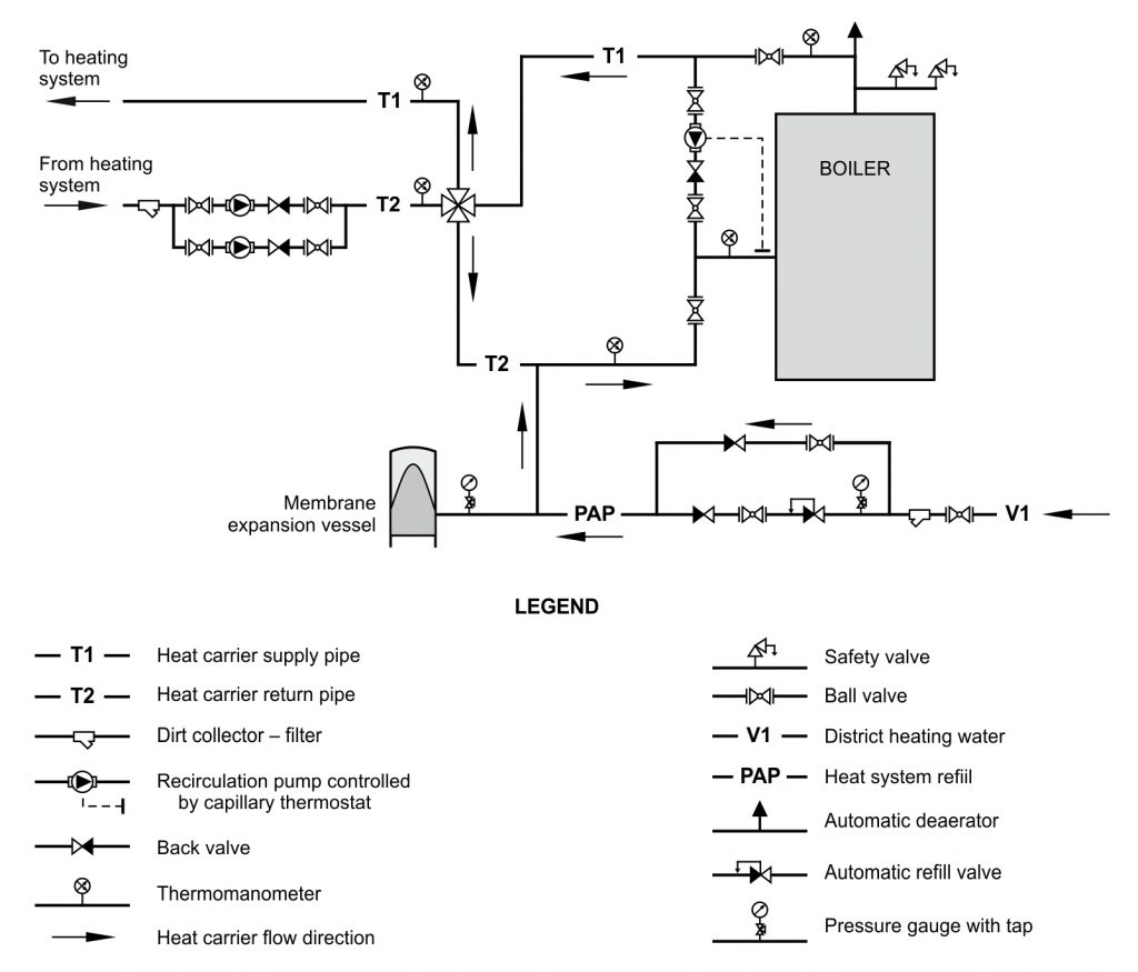
Recommended connection to the heating system diagram: